UNO board layout

ATmega328P (used on most recent boards) : 16Mhz, 8bit, 5V
1) Digital I/O Pins 14 (of which 6 provide PWM output)
Pins 1 and 0, marks as TF, RX cannot be used when connected to PC
2) Analog Input Pins 6 (DIP) or 8 (SMD)
3) 3 GND pins
4) DC Current per I/O Pin 40 mA
5) Flash Memory 32 KB
6) SRAM 2 KB
7) EEPROM 1KB
Another layout
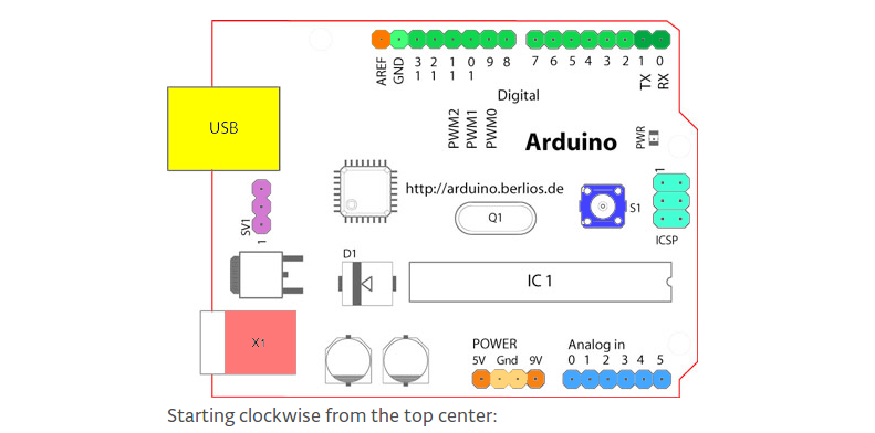
Starting clockwise from the top center:
Analog Reference pin (orange)
Digital Ground (light green)
Digital Pins 2-13 (green)
Digital Pins 0-1/Serial In/Out - TX/RX (dark green) - These pins cannot be used for digital i/o (digitalRead and digitalWrite) if you are also using serial communication (e.g. Serial.begin).
Reset Button - S1 (dark blue)
In-circuit Serial Programmer (blue-green)
Analog In Pins 0-5 (light blue)
Power and Ground Pins (power: orange, grounds: light orange)
External Power Supply In (9-12VDC) - X1 (pink)
Toggles External Power and USB Power (place jumper on two pins closest to desired supply) - SV1 (purple)
USB (used for uploading sketches to the board and for serial communication between the board and the computer; can be used to power the board) (yellow)