Communication protocols
For communicating with other devices like LED screen, accelerometer or other sophisticated sensors etc, there are several communication protocols. Multiple arduinos can also be connected in series. Establishing such communications with general purpose input output pins (GPIO) can be tedious. The common communication protocols in arduino family are listed below
Establishing communication through protocols:
1) Connect the protocol pins from arduino to the device
2) Connect the VCC and GND pin from arduino to the device
UART (Universal Synchronous Receiver Transmitter)
1) It allows to transmit and receive data at the same time. (Full duplex)
2) Protocol pins : Established through RX and TX pins.
3) Only one device can be connected for communication through these pins.
4) Default RX and TX are implemented at pin 0 and pin 1 respectively. These pins are connected to the chip (serial port) that enables USB communication with the computer. Therefore, pin 0 and pin 1 are not available when connected to a computer.
5) It is possible to use software serial library to implement UART interface at other pins. Then it is possible to have multiple devices communicating when connected to computer. But still, the arduino can communicate to only one device at a time
#include <SoftwareSerial.h>

        SoftwareSerial mySerial(10, 11); // RX, TX

        void setup() {
          // Open serial communications and wait for port to open:
          Serial.begin(57600);
          while (!Serial) {
            ; // wait for serial port to connect. Needed for native USB port only
          }


          Serial.println("Goodnight moon!");

          // set the data rate for the SoftwareSerial port
          mySerial.begin(4800);
          mySerial.println("Hello, world?");
        }

        void loop() { // run over and over
          if (mySerial.available()) {
            Serial.write(mySerial.read());
          }
          if (Serial.available()) {
            mySerial.write(Serial.read());
          }
        }
I2C (Inter Integrated circuit)
1) Also known as TWI (Two-wire interface)
2) It is Half duplex. That is, data can be only sent or received at a time.
3) Protocol pins :
SDA: Serial data line. (Also implemented on pin A4 in UNO)
SCL: Serial clock line. (Also implemented on pin A5 in UNO)
NOTE: There is only one I2C port in UNO. Analog pins are same as Serial pins.
4) Multiple devices (upto 127, corresponding to 7 bit address) can be connected in serial with the same pin. (if there are no address conflicts).
5) The connected devices are called slave device. Each slave device should have unique address. It is also possible to have multiple master devices controling a single slave device (like battery)
6) In some sensors, it is not possible to change this address. In some sensors, it possible to change this address by short circuiting certain lines as described in their datasheet.
When planning to use multiple I2C devices on a single board, make sure if they can be set to different addresses
7) Still, arduino can commuinicate with only one device at a time
8) To use I2C, we have to include Wire.h
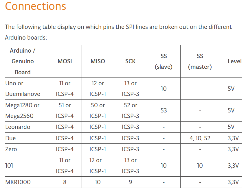
SPI (Serial peripheral interface)
1) It is a very fast serial full duplex communication.
2) Protocol pins: Connected to some digital IO pins
MOSI : Data line (Master out slave in), PIN 11
MISO : Data line (Master in slave out), PIN 12
SCK : Clock, PIN 13
SS: Slave select, PIN 10
The pins in arduino are assigned for this protocol with SPI library. If no SPI pins are specified in the datasheet of the module you are using, then these default pins should be used
3) When multiple devices are connected, the data and clock lines can be shared, but each slave should have separate Slave Select (SS) pin
4) Still, arduino can commuinicate with only one device at a time
5) Have to include SPI.h
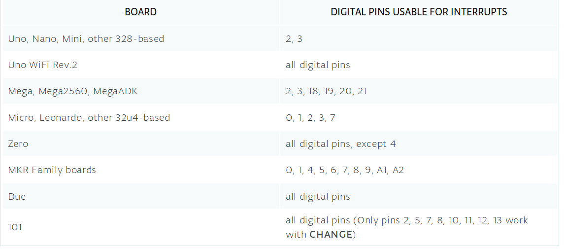
Interrupts
It is possible to implement an interupt, where the external device can stop the current opertions in arduino and run an interrupt code.
To allow interrupt, the module should have a dedicated interrupt (INT) pin. This pin should be connected to PIN 2 or 3 in arduino UNO
Click here for usage details
Using external hardware to communicate with micro controller
ICSP header (In Circuit Serial Programming)
1) These are the two sets of 2x3 pins on your UNO board.
2) It allows to attach a special hardware called hardware programmer, that allows you to directly program your microcontroller
3) There are two sets, because there are two MCs. One is the main MC ATmega328p. The other is for the USB controller