I2C Sensors
Two examples are demonstrated. One where I2C address cannot be changed and another one where it can be changed
For Adafruit breakout boards, if the I2C addrres can be changed, it will be mentioned in the technical details section of the product page
NOTE : It is not directly possible to connect two I2C devices with the same non editable address. Although there are workarounds, it may not be efficient.
When planning to use multiple I2C devices on a single board, make sure they have different addresses
NOTE: Check the Operating voltage before connecting any devices
Default I2C address can be found in the product page or in the library's header file. If it is getting tedious, use I2C scanner sketch, which will scan all I2C address and find the address where the device is located.
To use I2C, we have to import Wire.h
1) Adafruit TCS34715 RGB Sensor
Product page: Click here
Library : git hub repo
I2C address is Not changable. The default address used by the device is 0x29 which can be found in the product page, or from the Adafruit_TCS34725.h file from the library
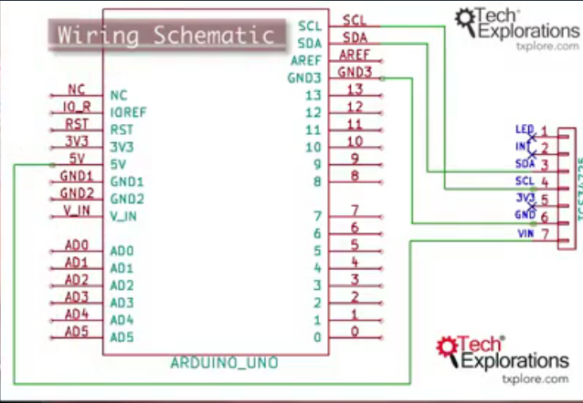
Circuit
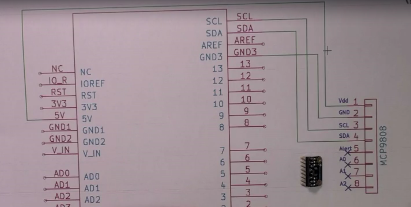
2) Adafruit High accuracy temperature sensor MCP9808
Product page: Click here
Library : git hub repo
The technical specification says, I2C can be any address inbetween 0x18 - 0x1F (0x18 is the default address in the library's header file). To find the hexadecimal numbers between two, click here
When you change the I2C address, the hardware connections should be changed. (Eg, certain pins should be short circuited)
Changing I2C address
To do this, refer the datasheet and check for PIN descriptions and see if it has any pin assiged to be as a slave address
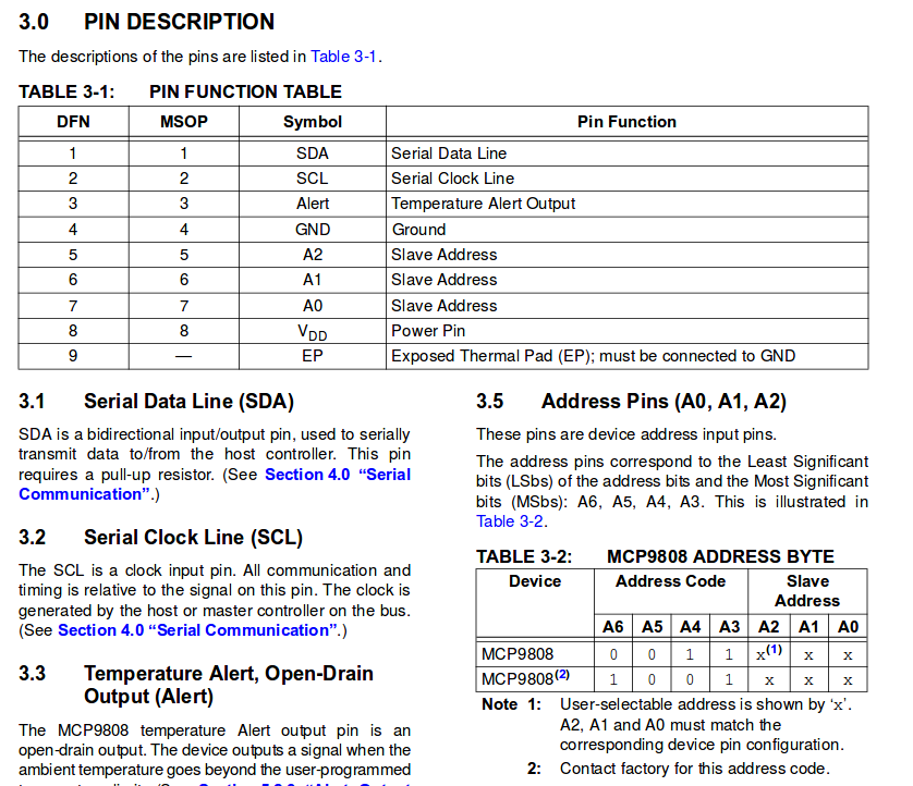
According to this documentation, A2, A1, A0 are the pins in the device to be used for slave address that can be changed by user. The address pins A3 - A3 cannot be changed
By default, these pins are set to LOW. This can be checked by converting 0011000 to hex gives the default address 0x18.
To change address to 0011001, we have to set A0 to HIGH by connecting A0 pin in the device to VCC
Circuit with default slave address 0x18